CS184/284A Spring 2025 Homework 4 Write-Up
Link to webpage: hw4.html
Link to GitHub repository: github.com/cal-cs184-student/sp25-hw4-leov

Overview
In this project, I built a physically based cloth simulation using a mass-spring model with structural, shearing, and bending constraints. I experimented with parameters like spring constant, density, and damping to observe their effects on cloth behavior, capturing how stiffness and weight impact motion and settling. I implemented collisions with spheres and planes, as well as self-collisions using spatial hashing, and tested how different values affect folding and interaction. On the rendering side, I used shaders to apply Blinn-Phong lighting, texture mapping, bump and displacement mapping, and mirror effects. This project deepened my understanding of both simulation stability and shader-based visual effects.
Part 1: Masses and springs
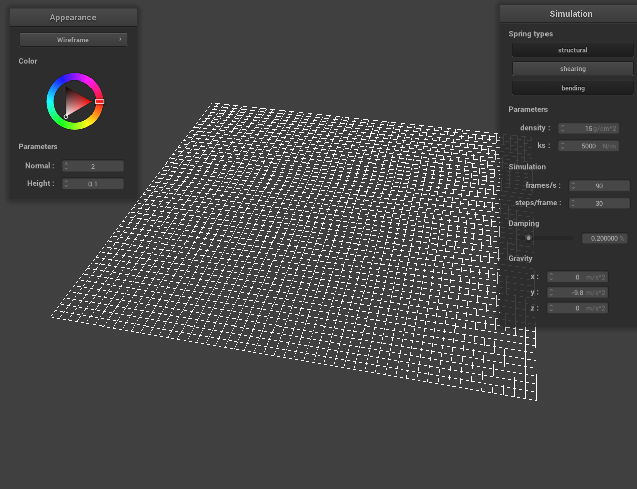
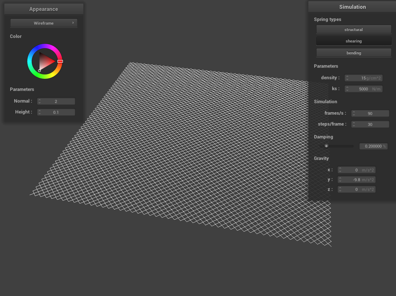
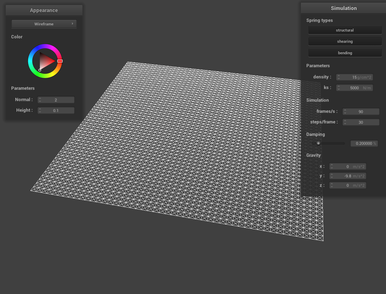
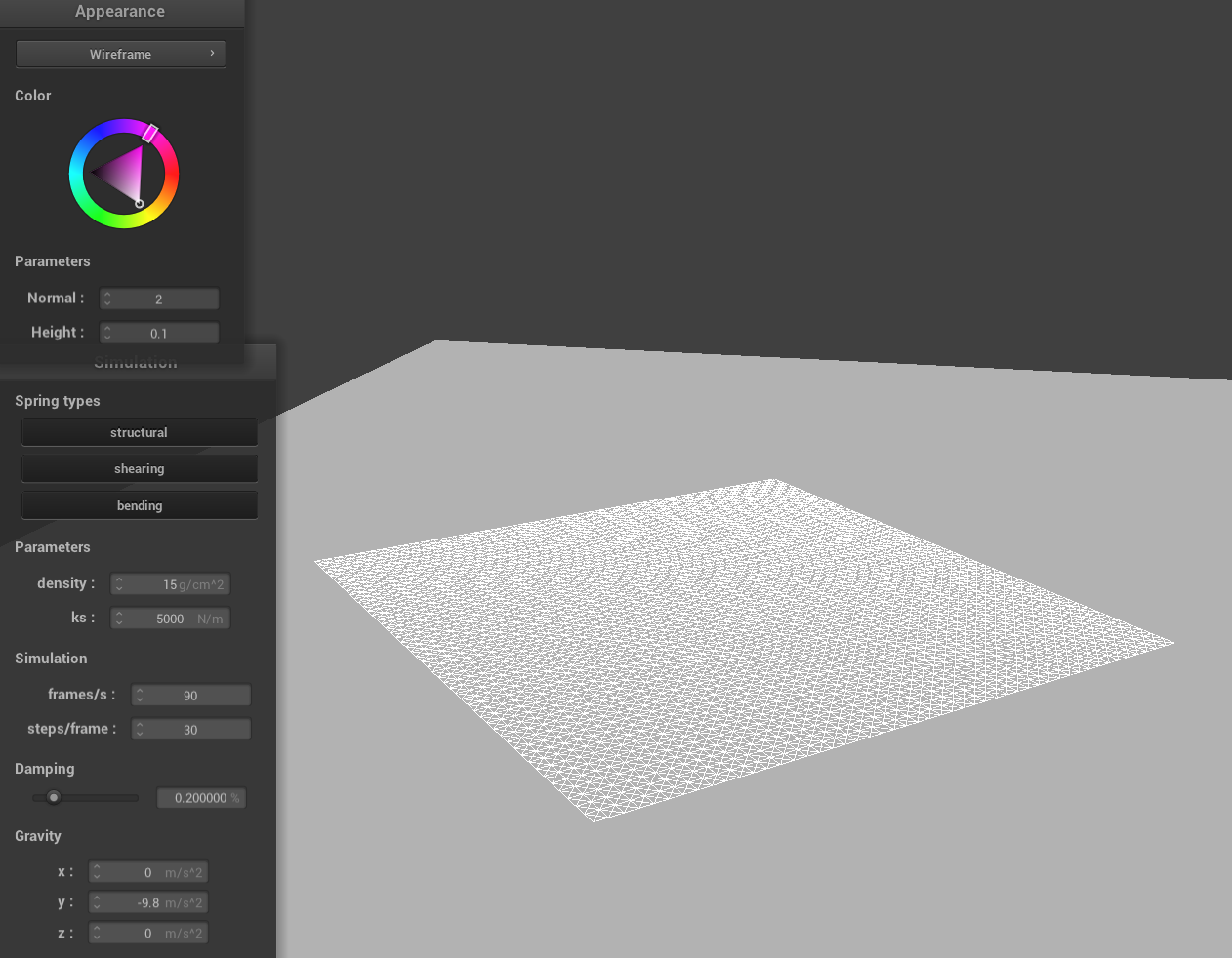
Here is a screenshot of scene/pinned2.json where you can clearly see the cloth wireframe which shows the structure of my point masses and springs.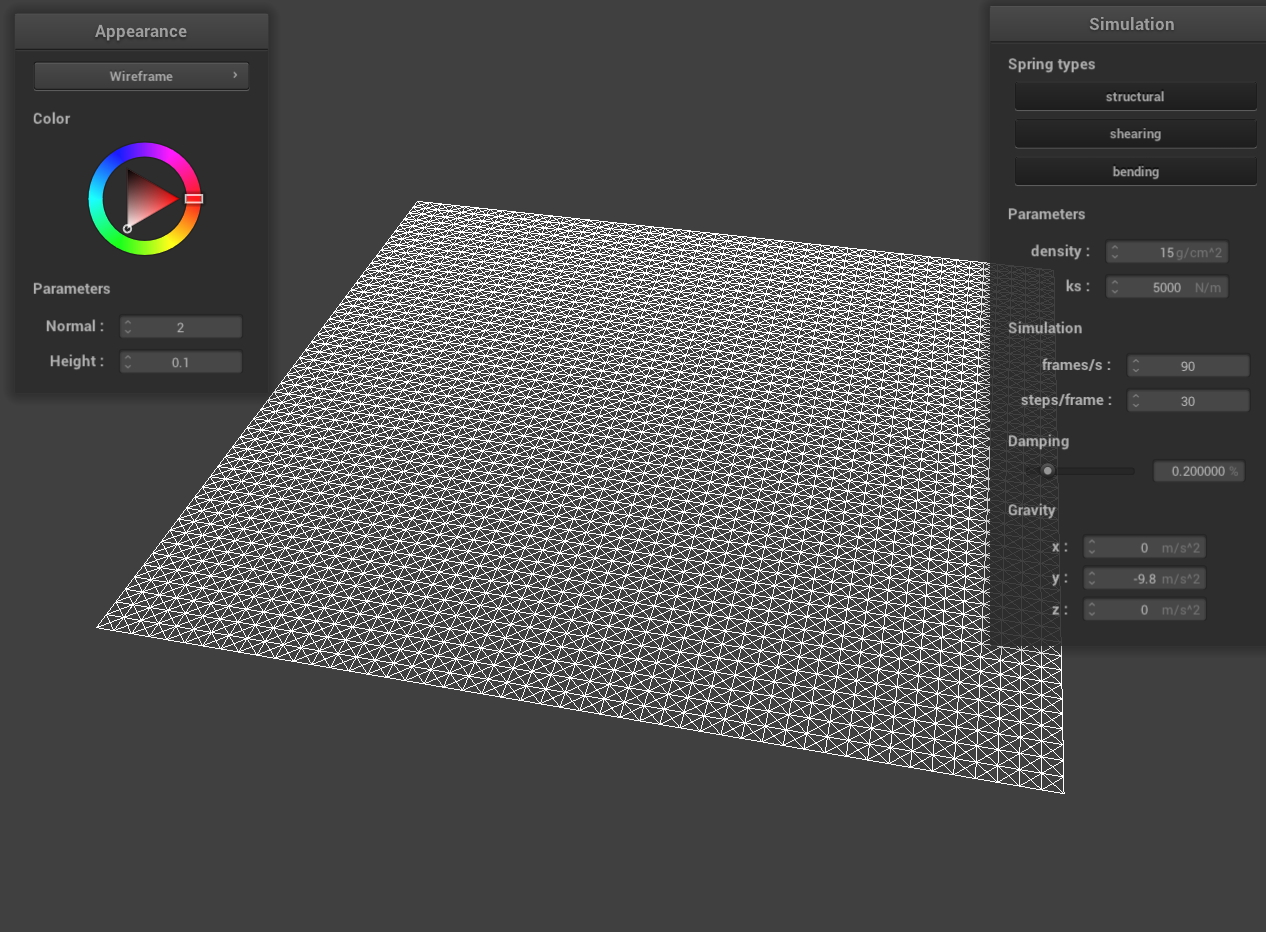
|
|
|
Part 2: Simulation via numerical integration
Here I experimented with some the parameters in the simulation.
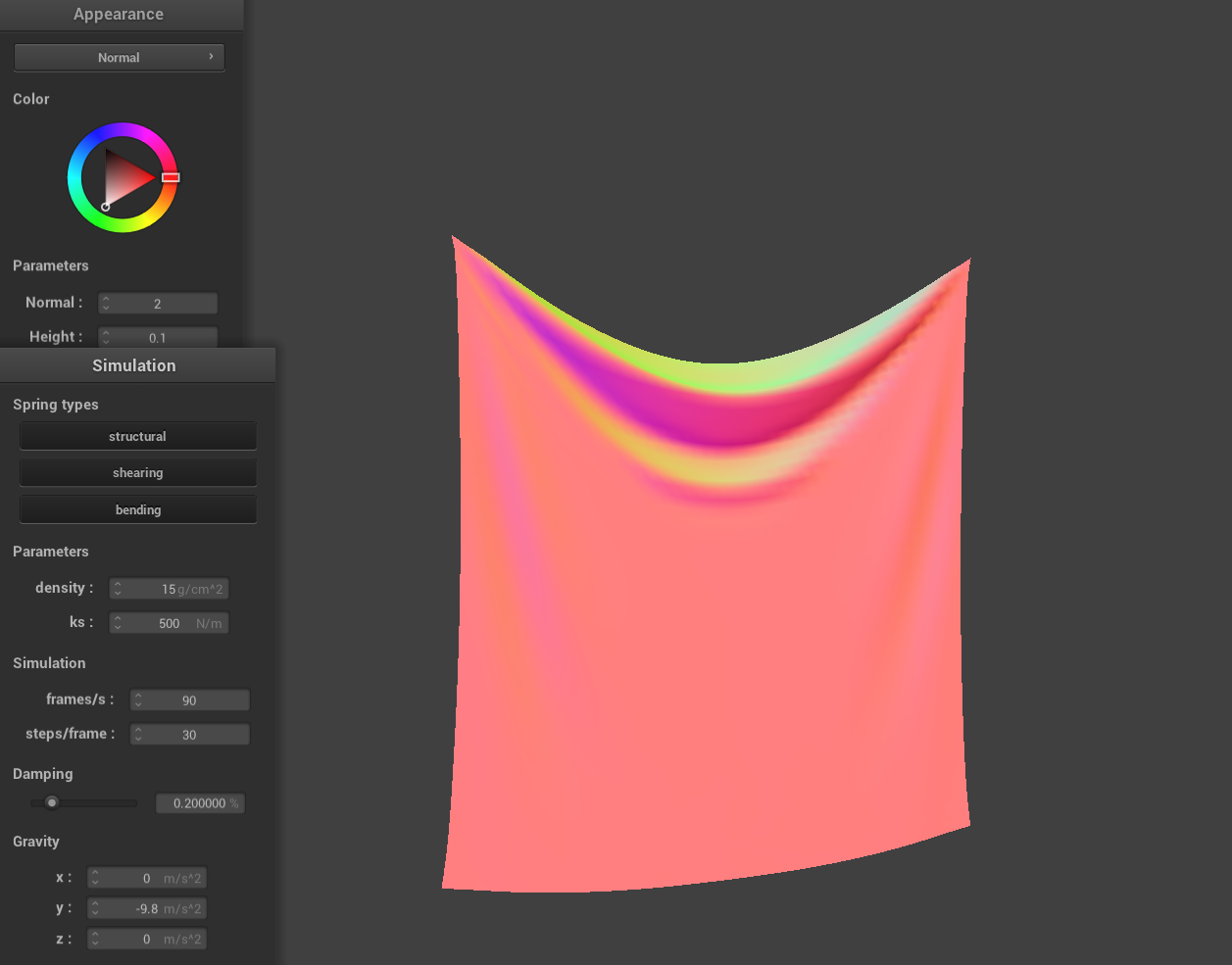
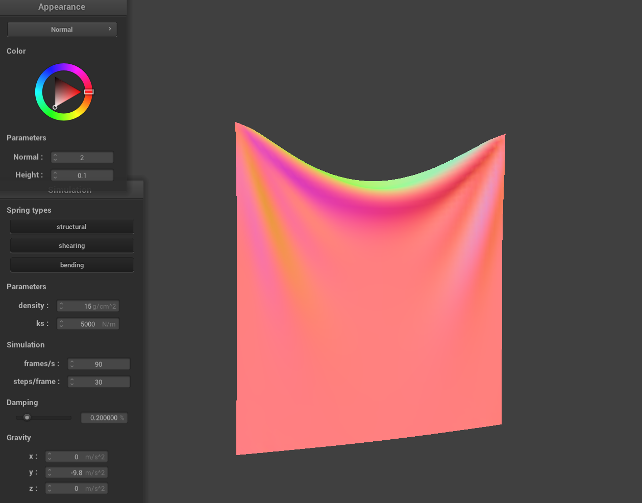
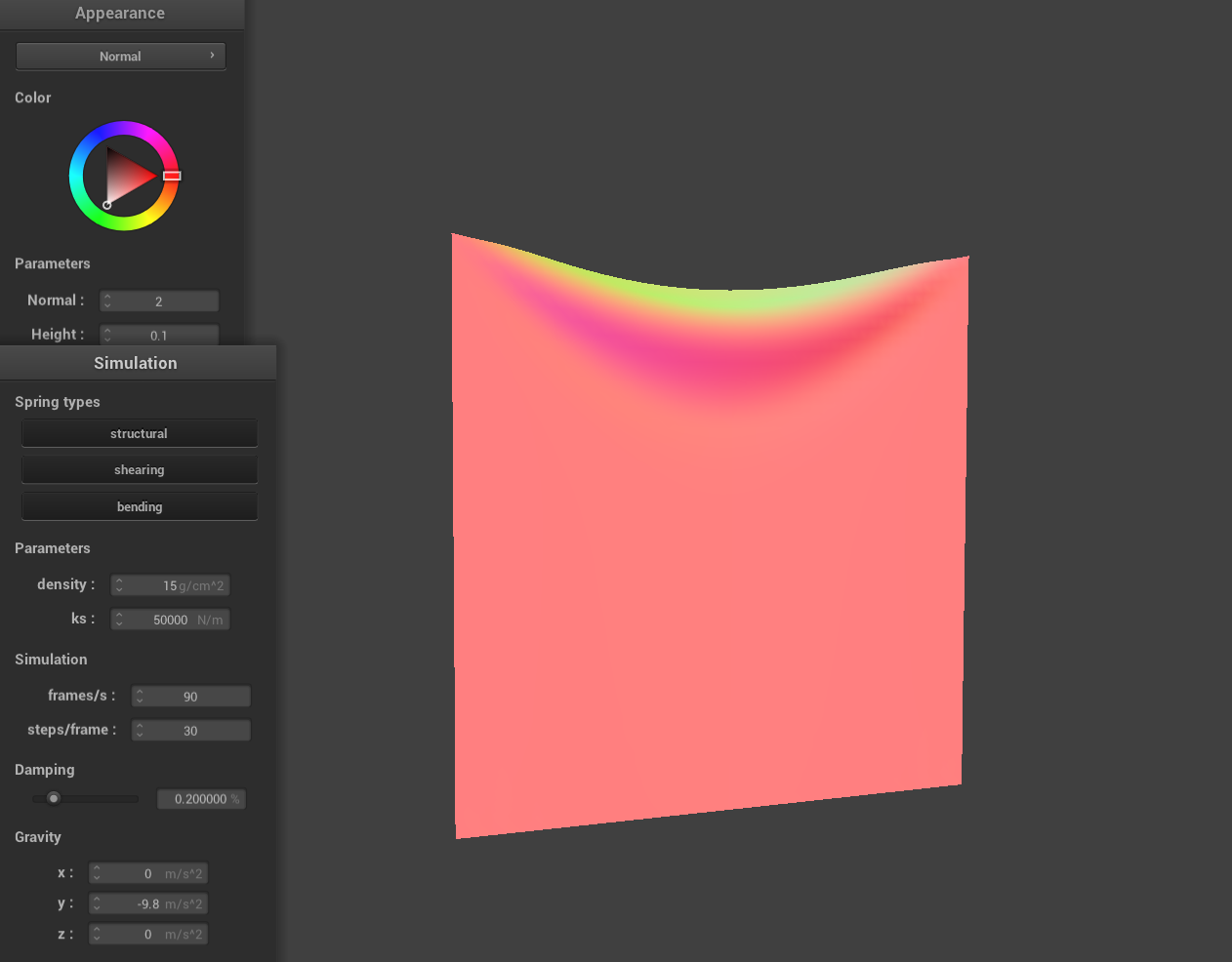
Spring Constant
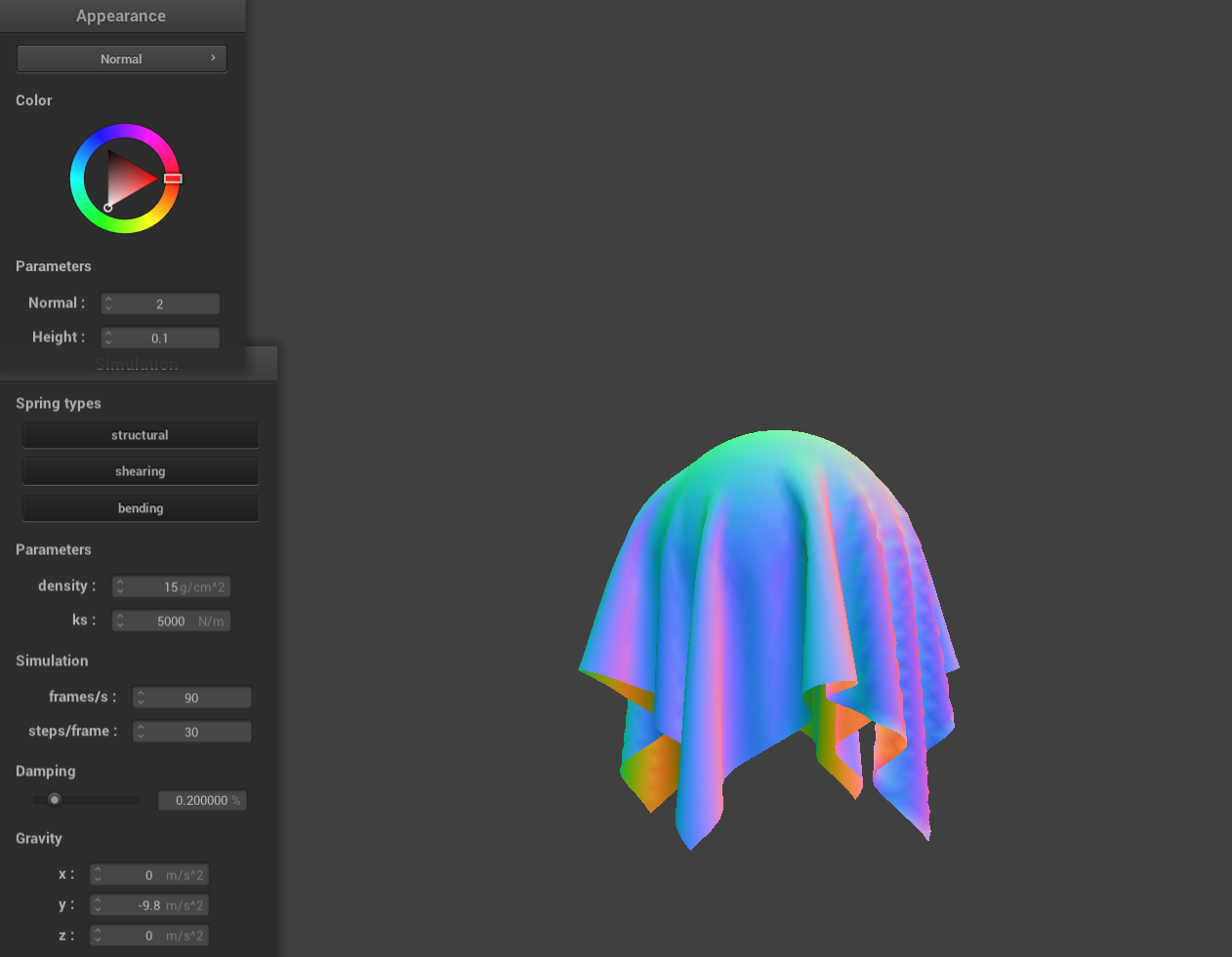
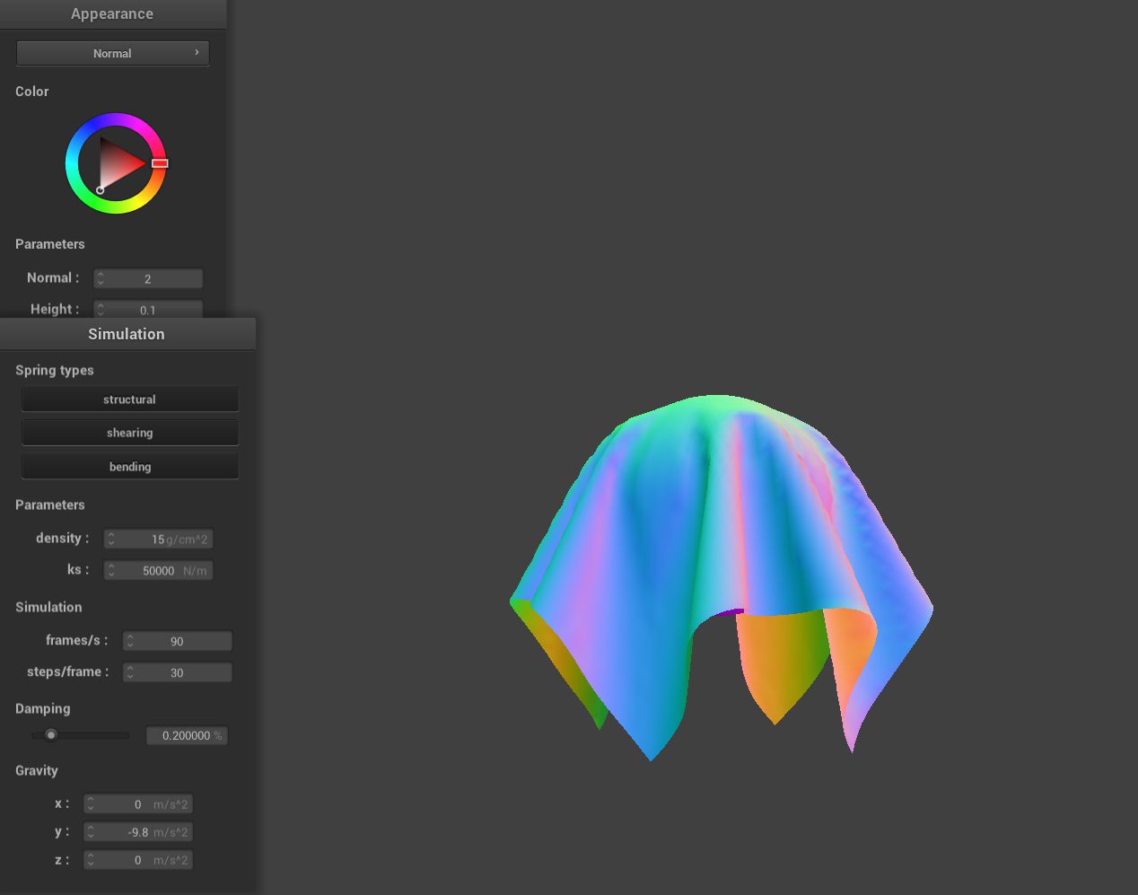
As the spring constant decreases, the spring gets less stiff. Looking at the images from left to right, you can see that the spring constant increases by a factor of 10 each time. The cloth looks a lot more flexible with the lower spring constant, when \(k=500\) it stretches much more compared to when \(k=50000\) even though gravity is the same in both simulations.
|
|
|
|
|
|
Density
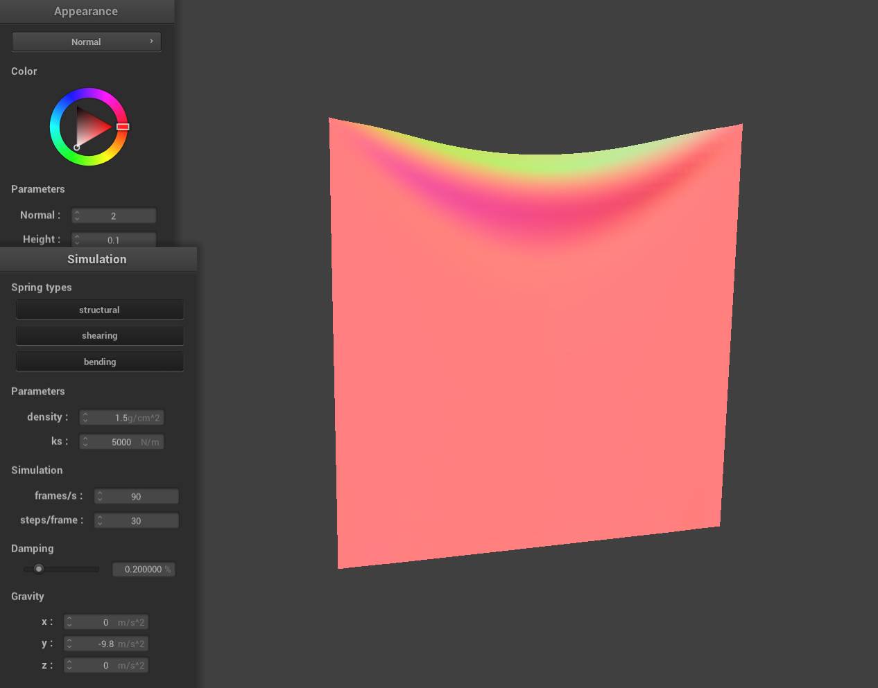
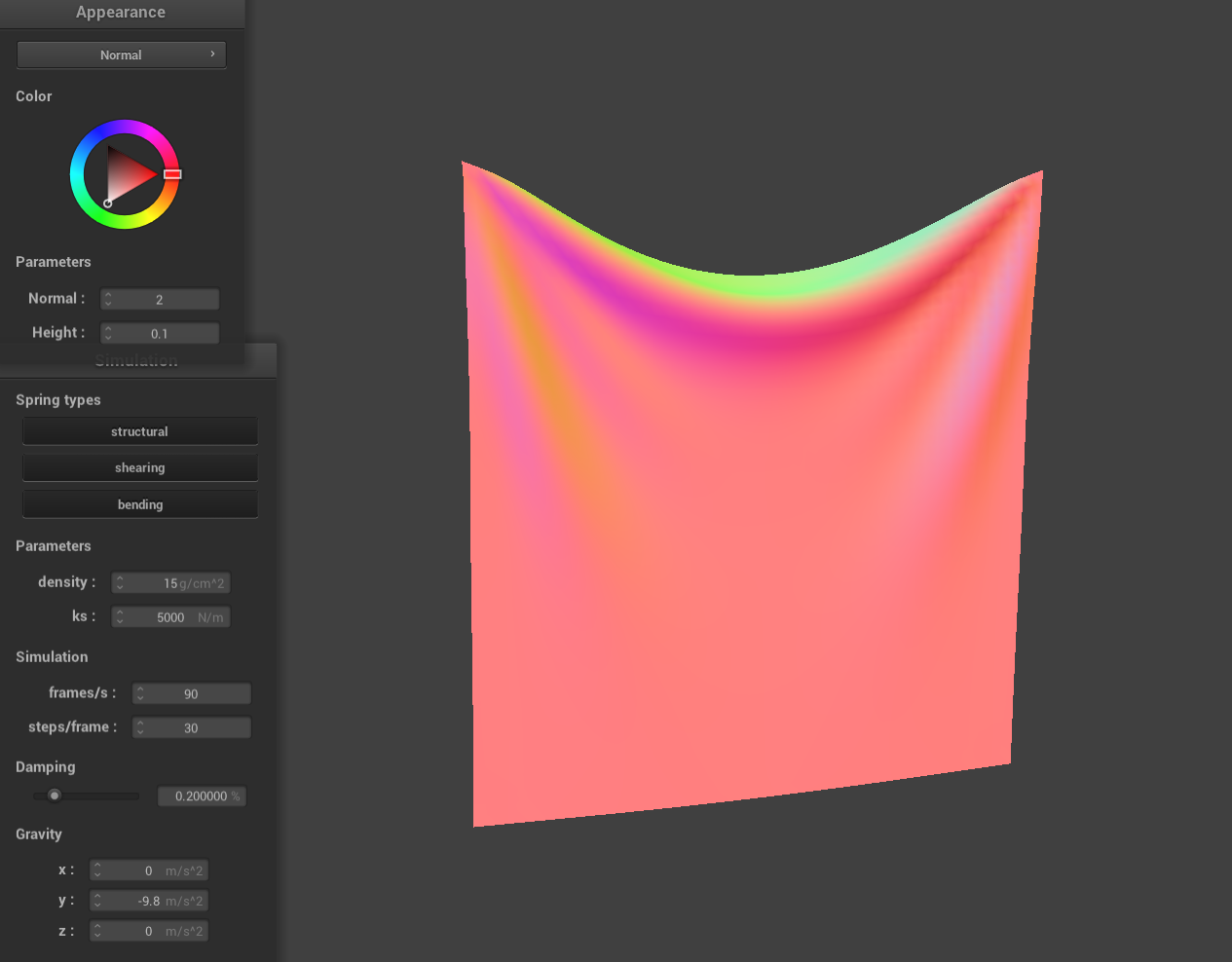
Density is a property of the point masses, not the springs. Increasing the density affects the cloth in a similar way to lowering the spring constant. The effect also seems similar to the spring case just inversely so hence the images being in a "reverse" order. This makes sense when you consider Newton's Second Law, which says that force is proportional to mass. So, with greater density, the cloth becomes more responsive to external forces—like gravity—in the simulation.
|
|
|
|
|
|
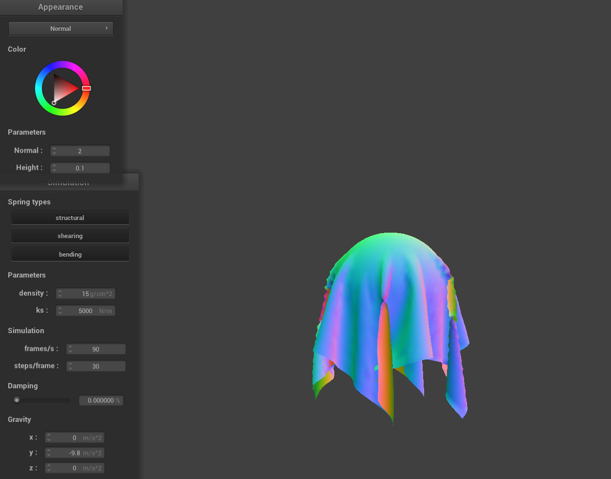
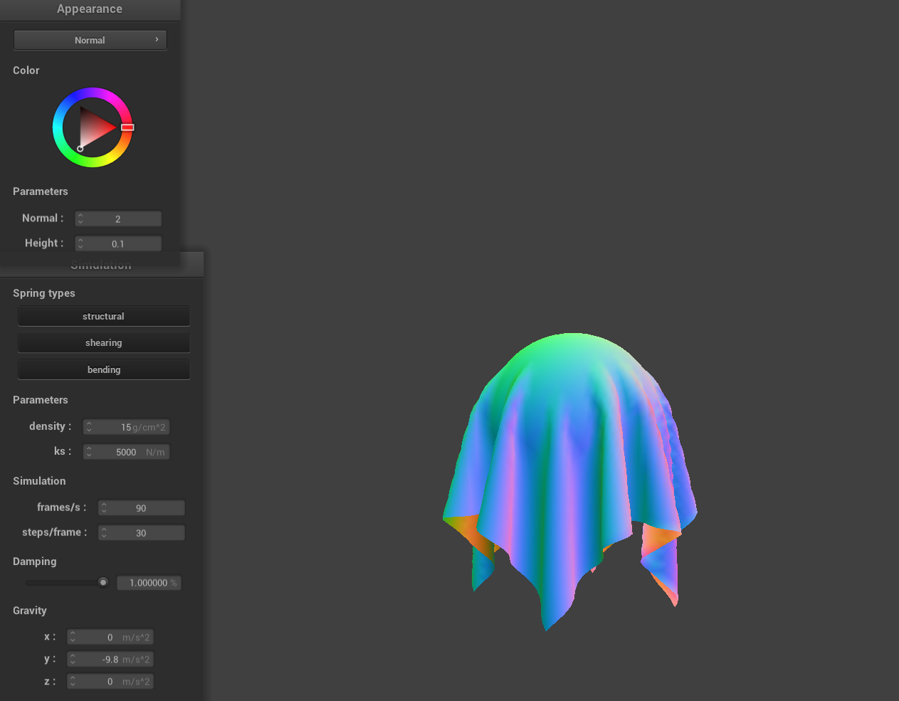
Damping
The effect of damping isn't as clear in still images but when watching the real time simulation it plays a big role in how quickly the system settles. Higher damping values help the cloth come to rest faster. Both images shown were taken after long simulation times. In the left image, with 0% damping, the cloth never fully settles—small where we can small ripples and oscillations remain, even after a long time. In contrast, the right image, with 1% damping, shows a cloth that has completely settled, as you can tell from its smooth, undisturbed shape. This is because small changes in the cloth arent just damped but persist for 0% damping.
|
|
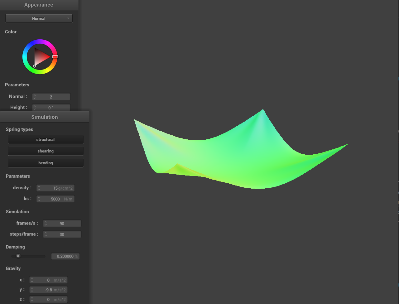
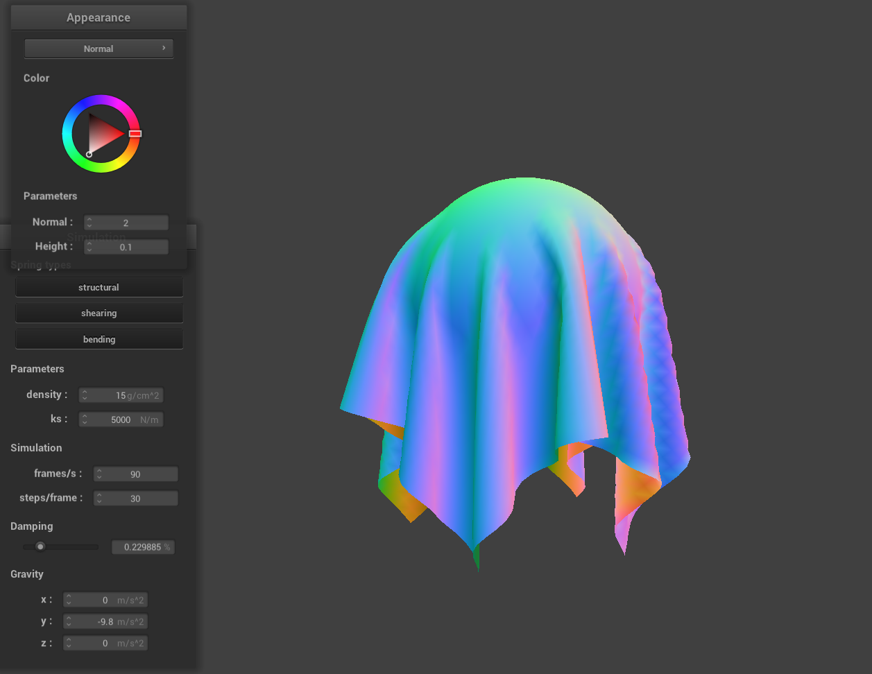
Here is a picture of the 4 pinned corners shaded cloth in its final resting state.
Part 3: Handling collisions with other objects
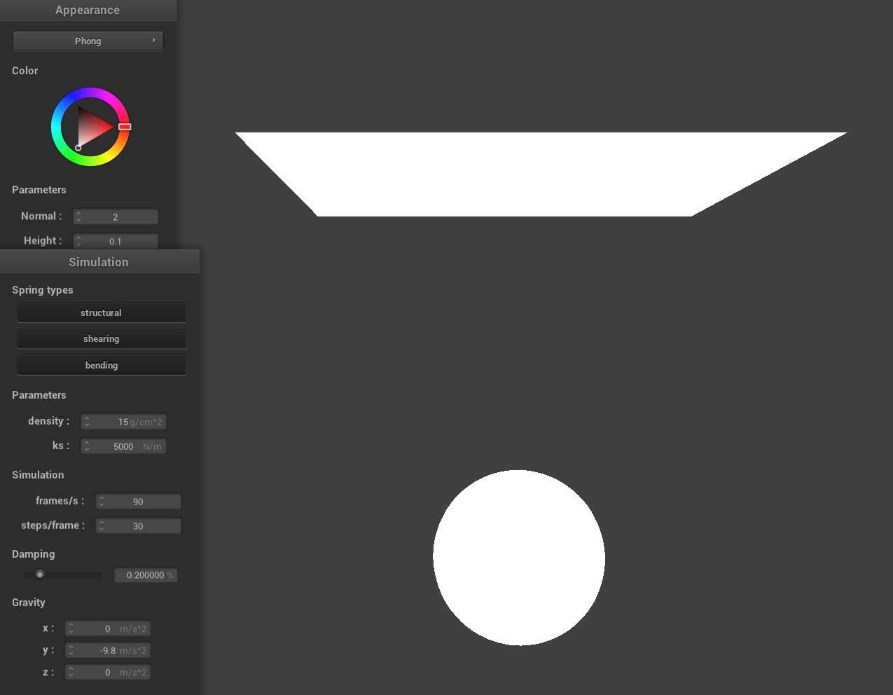
Here I implemented collisions with spheres and planes.Spheres:
It checks if the point mass is inside the sphere by comparing the squared distance from the sphere's center with the squared radius. If the point is inside, it is projected outwards to the sphere's surface, using the appropriate direction vector with friction applied to dampen the movement.
Planes:
The algorithm checks if the point mass is below the plane (using the dot product with the normal). If so, it moves it along the plane normal to just above the plane (with a SURFACE_OFFSET) and adjusts the movement based on friction, ensuring the point mass doesn't "stick" unrealistically.
|
|
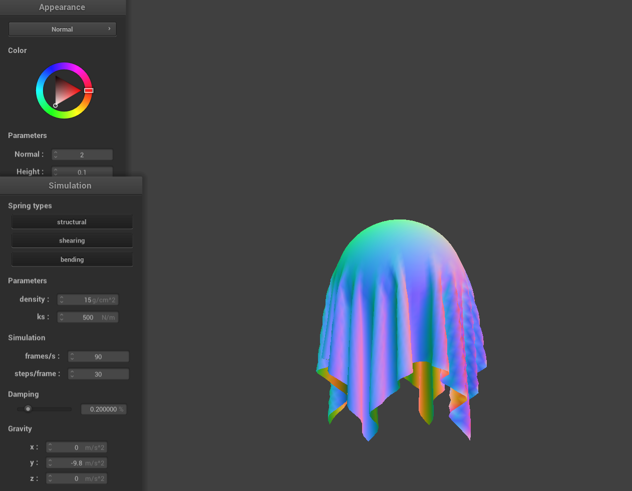
Part 4: Handling self-collisions
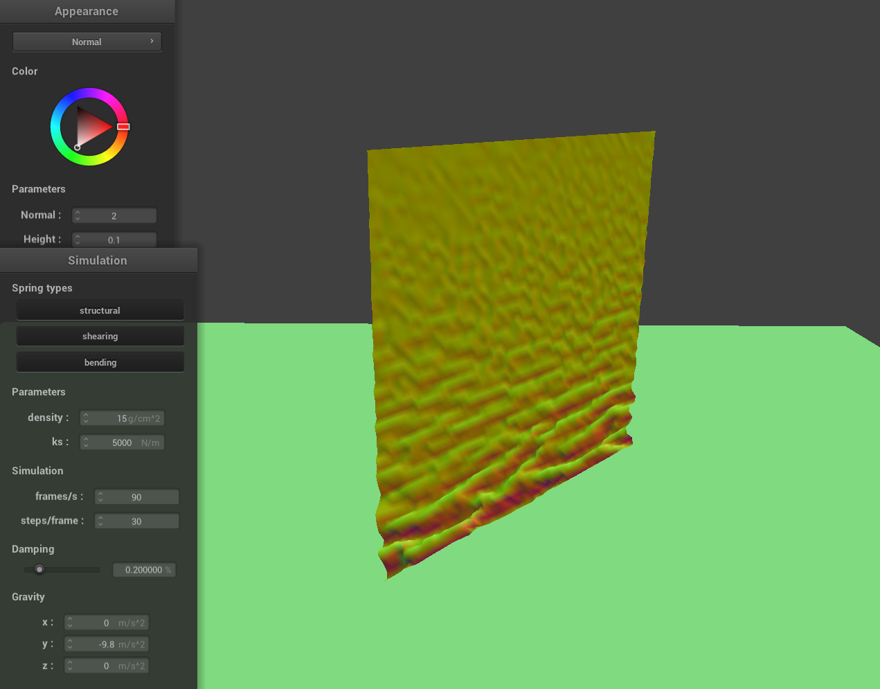
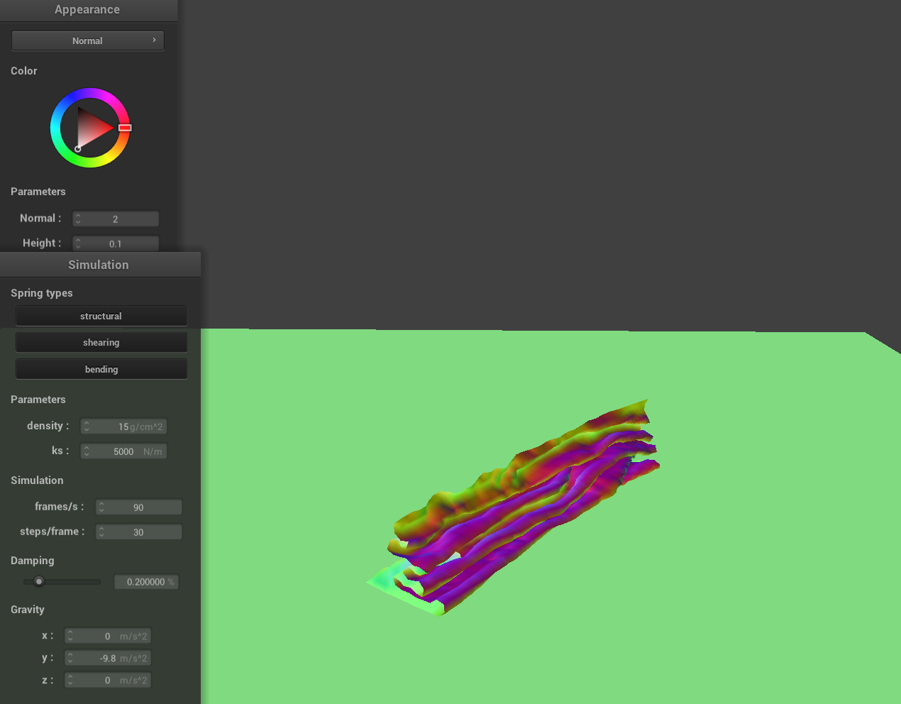
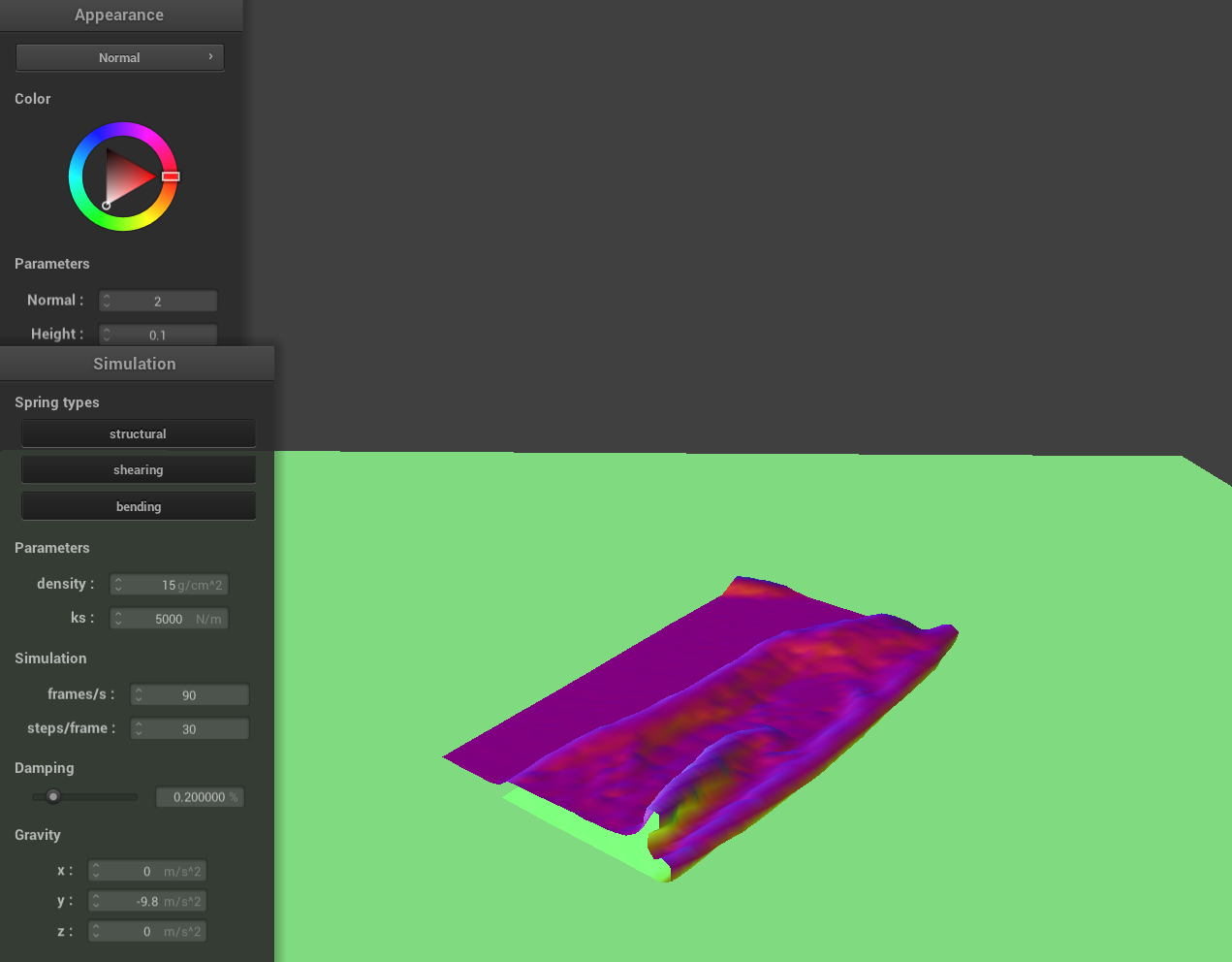
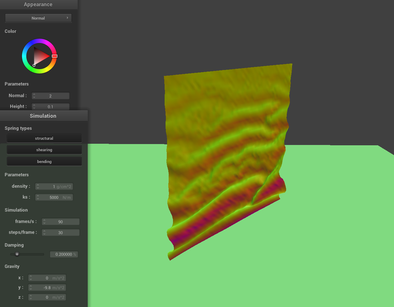
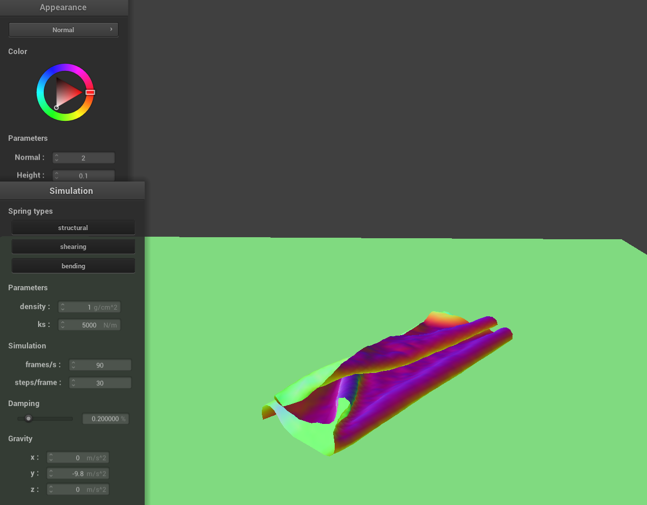
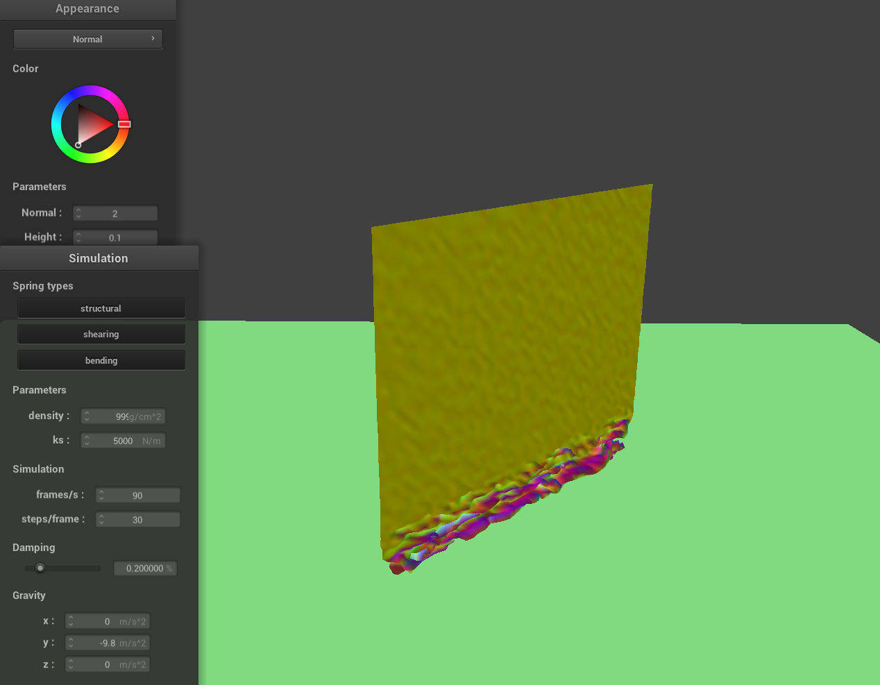
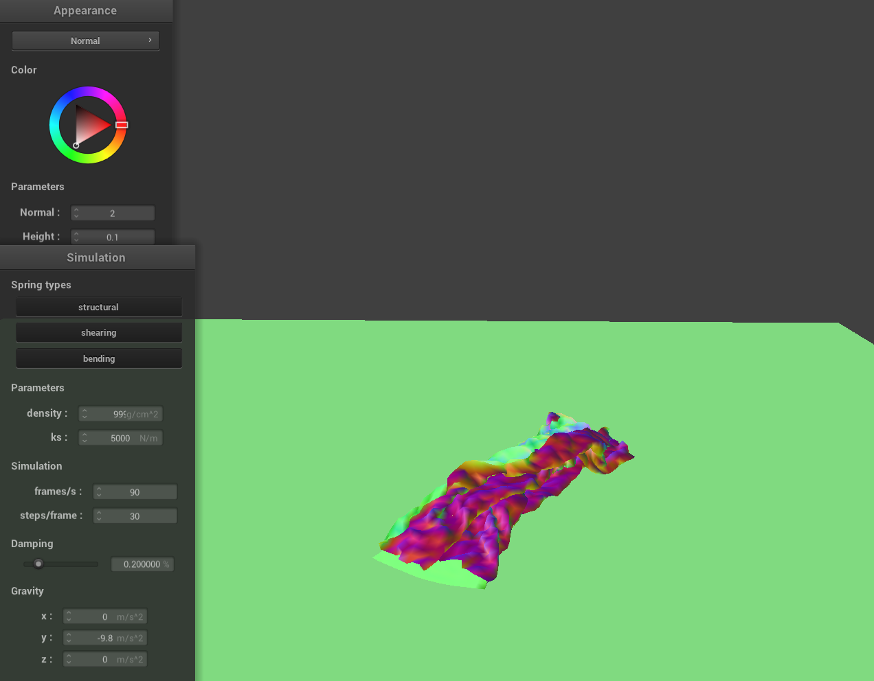
To handle self-collisions, I implemented a method that checks whether a given point mass is too close to any other point masses within the same spatial hash cell. First, the point mass is hashed based on its position to quickly retrieve a set of nearby candidates. For each candidate, I check whether it is within a distance of 2 * thickness and ensure it is not the same point mass. If a collision is detected, I compute a correction vector that would push the point mass away from the candidate so that they are exactly 2 * thickness apart. I accumulate these correction vectors and average them across all detected collisions. To maintain stability over time, the resulting correction is scaled down by the number of simulation steps before being applied to the point mass's position.Here are a few screenshots that document how my cloth falls and folds on itself, starting with an early, initial self-collision and ending with the cloth at a more restful state.
|
|
|
High ks and low density are similar, and same vice versa.
|
|
|
|
|
|

|
|
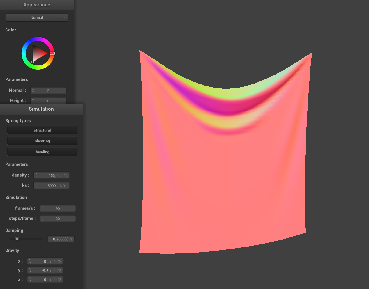
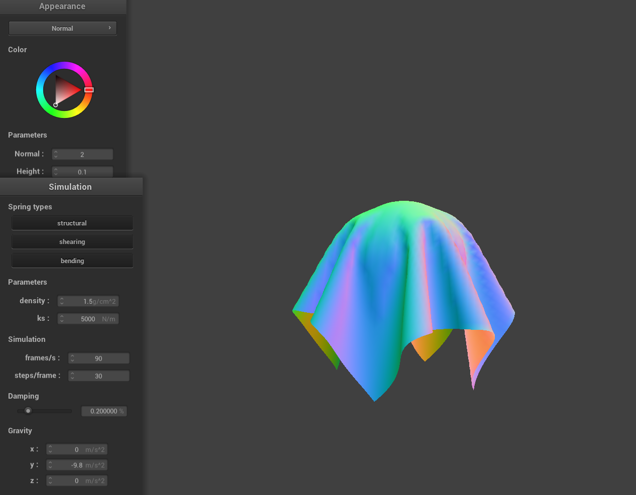
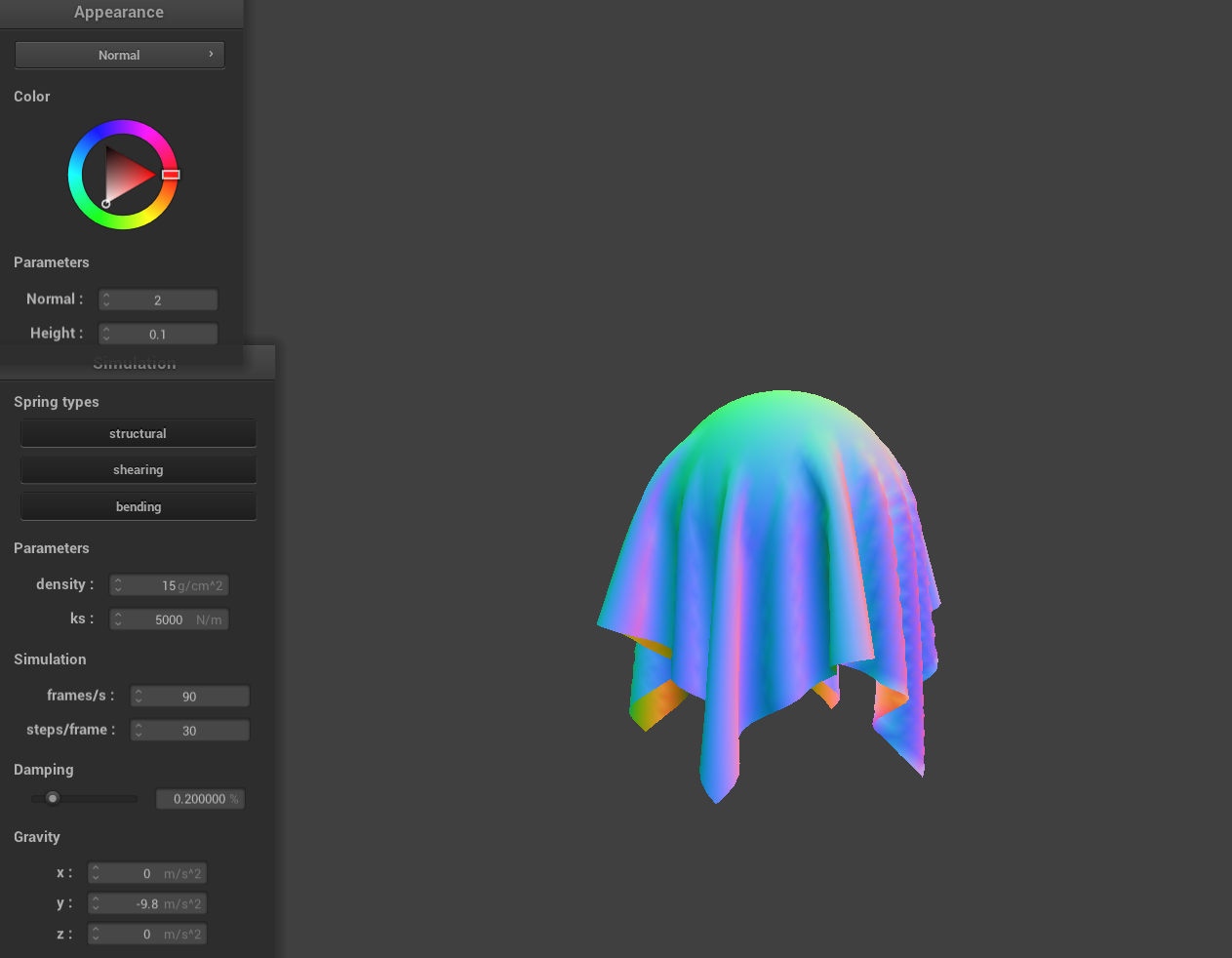
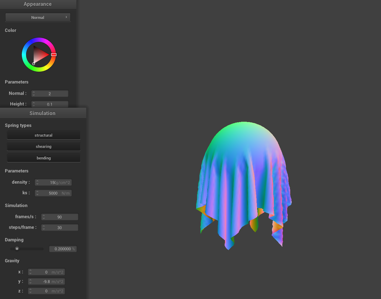
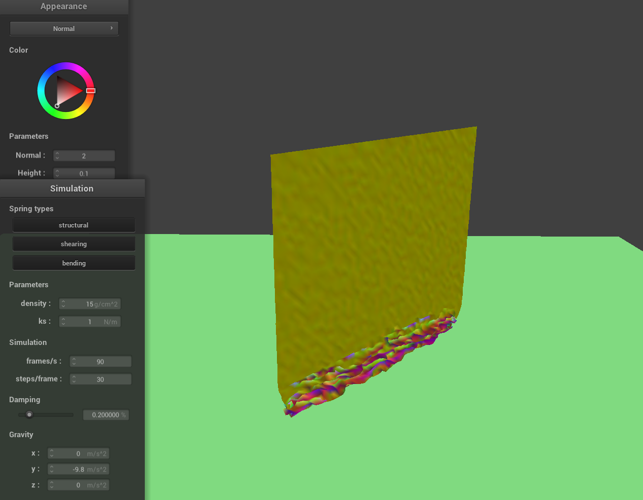
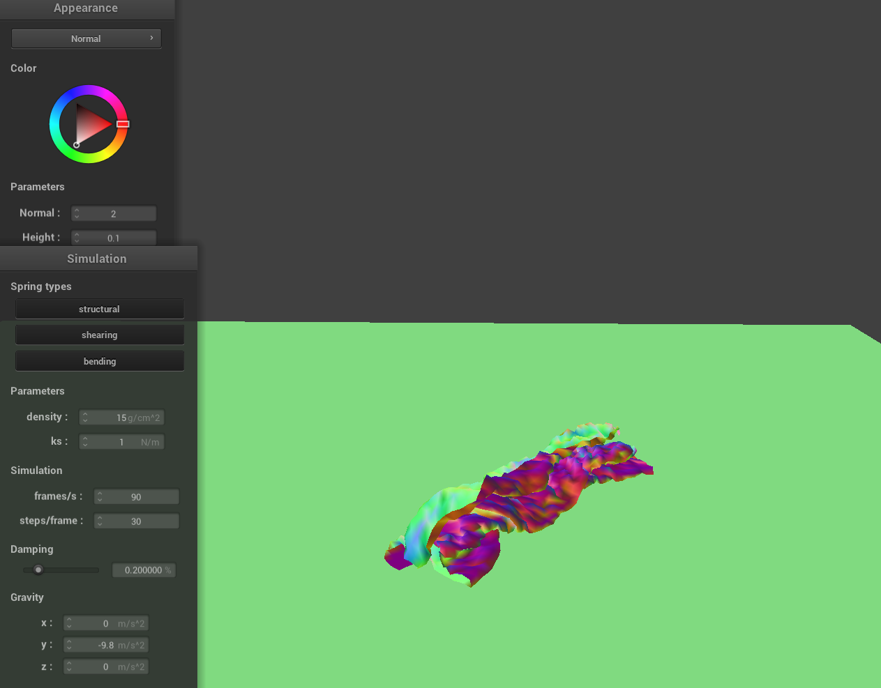
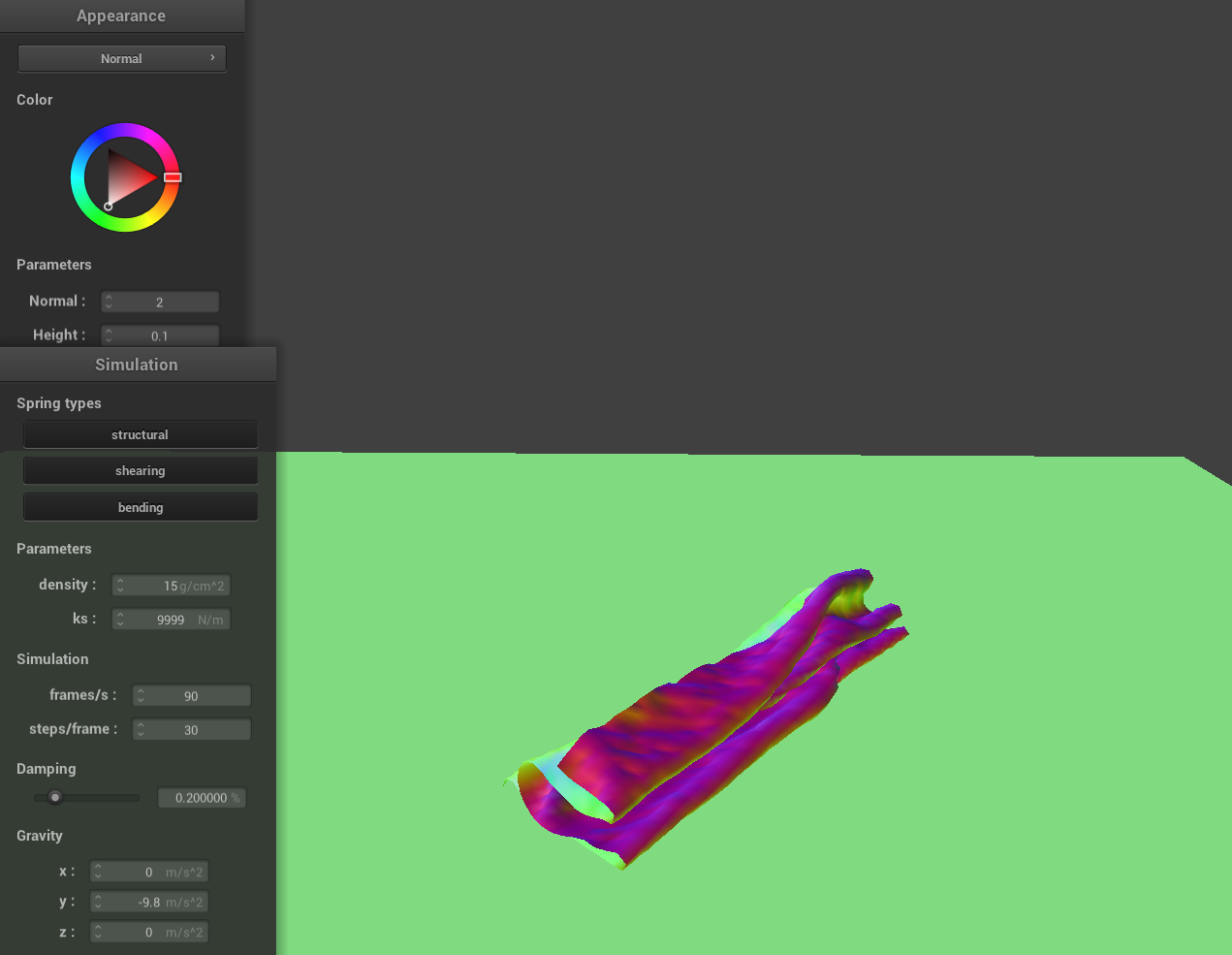
As we vary the density and the ks of the cloth, we observe distinct differences in how the cloth behaves as it falls and interacts with itself. For low density and high ks values, the cloth appears smooth and rigid. The low density means the cloth has less mass pulling it downward due to gravity, and the high stiffness resists deformation, so the cloth maintains its shape more effectively. As a result, the fabric falls gently and drapes with minimal wrinkles, almost like a lightweight sheet of stiff paper. Conversely, for high density and low ks values, the cloth appears crumpled or 'crunchy'. The higher density increases the gravitational force acting on the cloth, pulling it down more aggressively, while the low stiffness means the springs can't strongly resist deformation. This leads to more pronounced folds, wrinkles, and intersections as the cloth collapses onto itself, resembling a soft and heavy fabric like velvet or a thick curtain.
Part 5: Shaders
A shader program is a set of instructions executed on the graphics processing unit (GPU) to control the rendering of objects on the screen, often written in a shading language like GLSL. The program is typically divided into two primary sections that work together:
Vertex Shader
This stage operates on individual vertices. Its core responsibility is to take the raw vertex data (such as position, normal vectors, and texture coordinates) and transform it into a coordinate system suitable for display—typically converting the data to normalized device coordinates. Essentially, the vertex shader lays the groundwork by positioning each vertex within the 3D space and passing along data necessary for later stages.
Fragment Shader
After the vertices have been processed and positioned, the fragment shader takes over to determine the final color and appearance of each pixel (or fragment) that will be displayed. It uses interpolated data from the vertex shader—such as texture coordinates and color—and applies material properties and lighting effects (like specular highlights or diffuse reflections) to create realistic imagery. This process efficiently simulates detailed material and lighting effects.
Together, the vertex and fragment shaders form a powerful rendering pipeline. By combining geometric transformations with color and lighting computations, shader programs deliver realistic material appearances in real time without the high computational cost of techniques like exhaustive ray tracing.
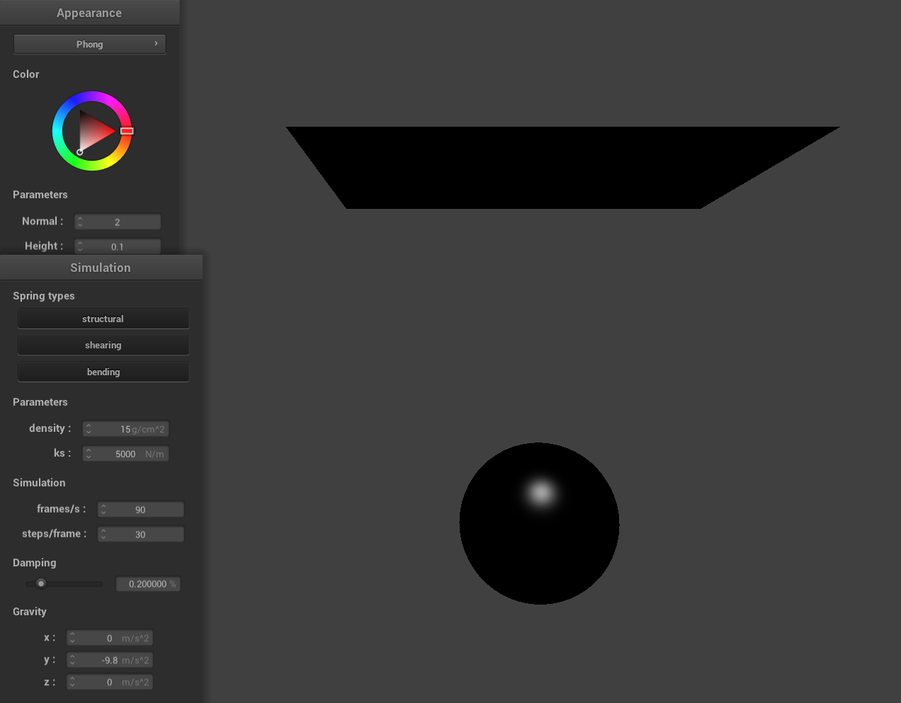
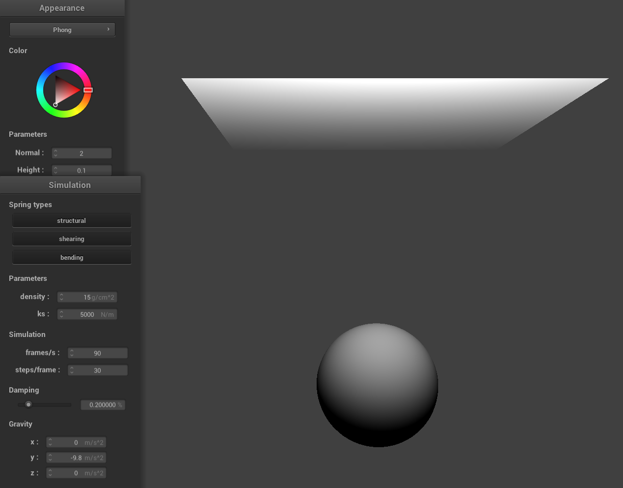
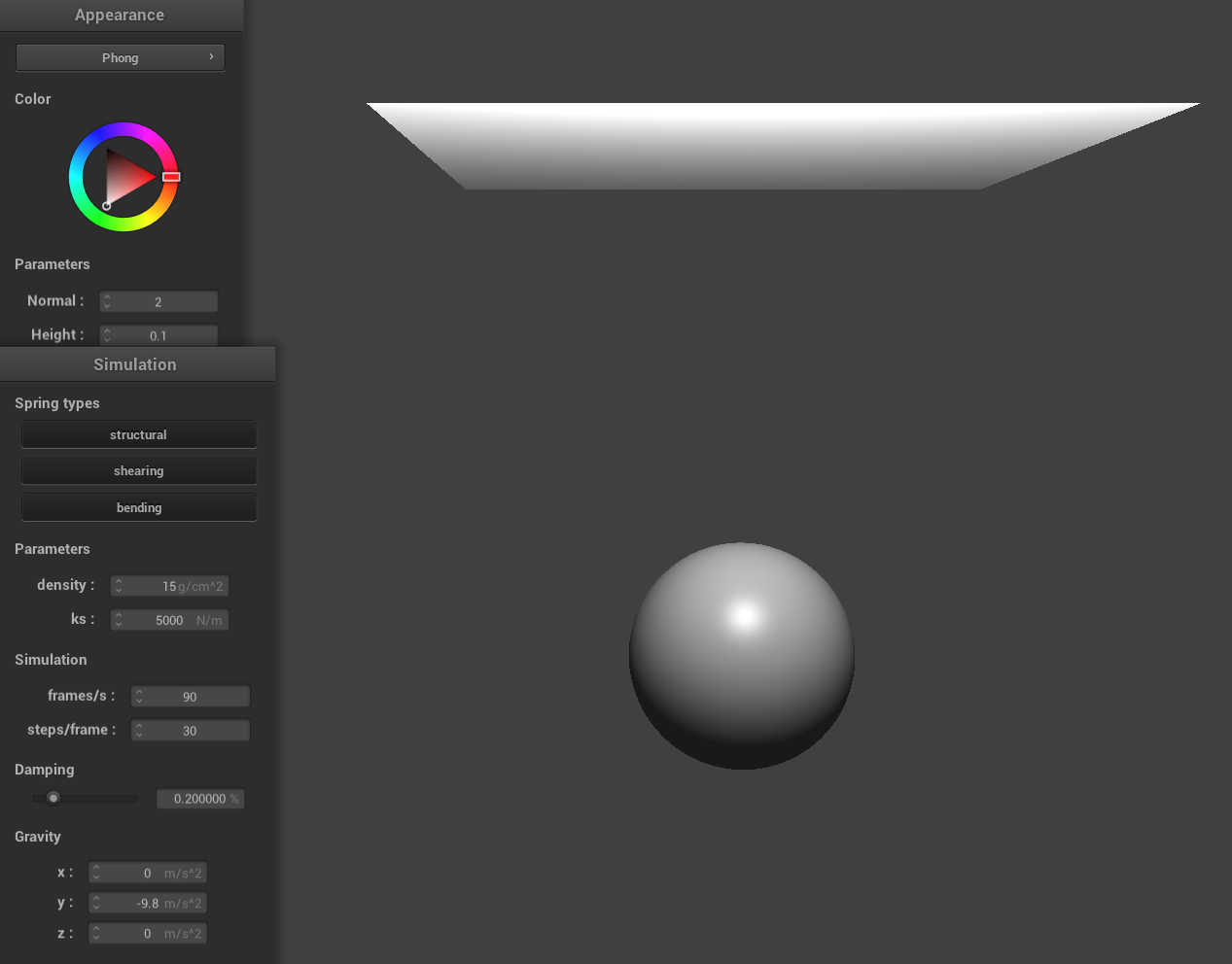
Blinn-Phong Shading
The Blinn-Phong shading model simulates how light interacts with surfaces by combining three lighting components: ambient, diffuse, and specular.
- Ambient: A constant, low-level light that illuminates all parts of a scene uniformly, ensuring that surfaces are never completely dark.
- Diffuse: Light scattered in many directions when it hits a rough surface, dependent on the angle between the light and the surface normal, which gives objects their overall brightness.
- Specular: The bright highlights on a surface, calculated using a halfway vector (the normalized average of the light and view directions), simulating glossy, mirror-like reflections.
|
|
|
|
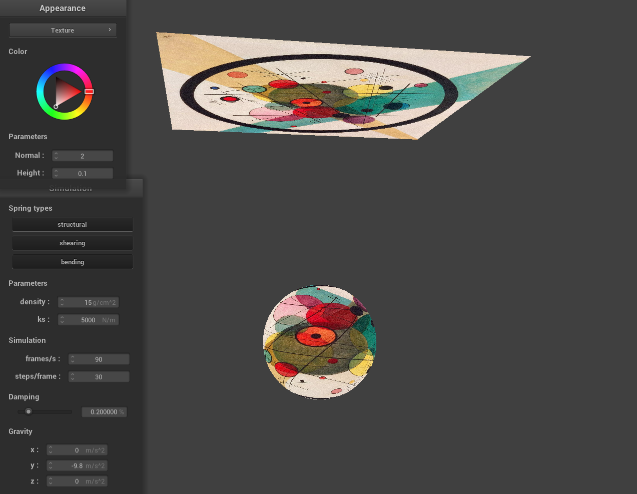
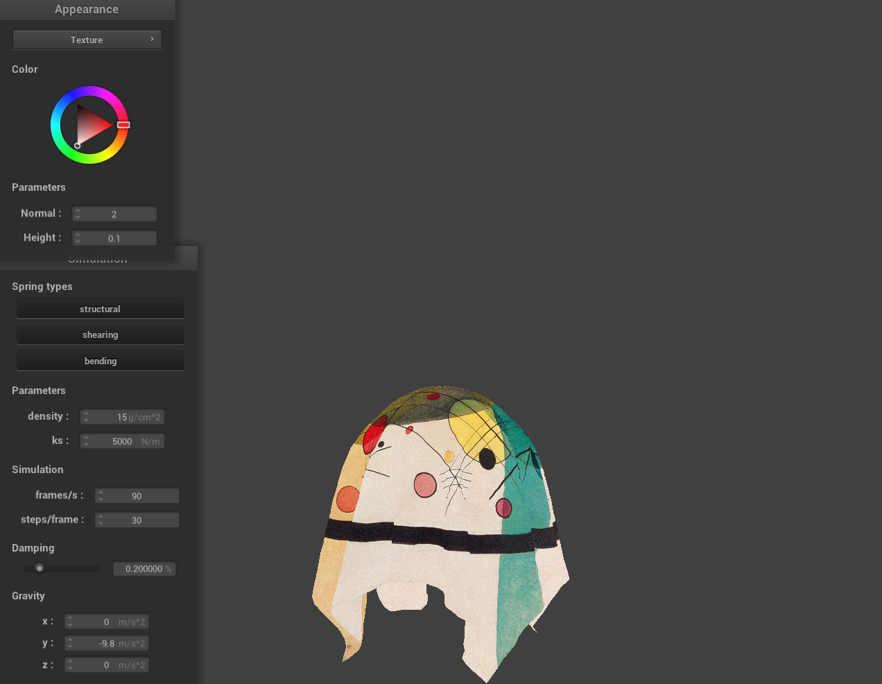
Texture Mapping Shader Using Custom Texture
|
|
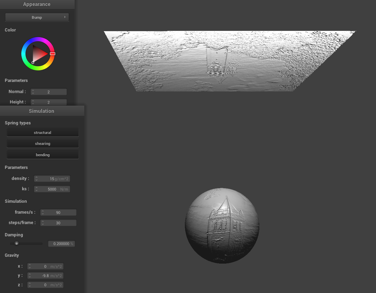
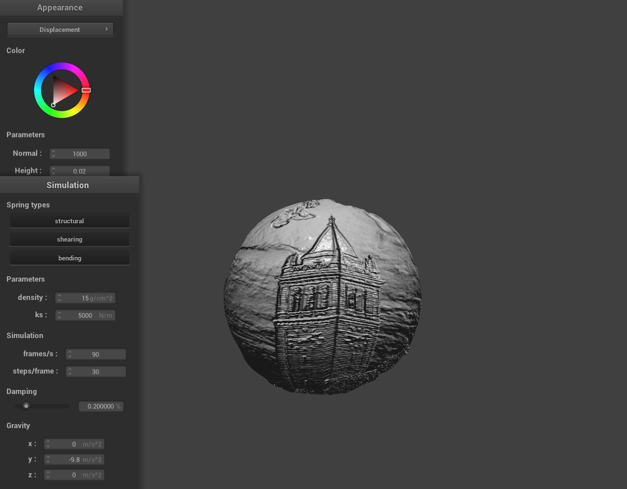
Bump and Displacement Shader
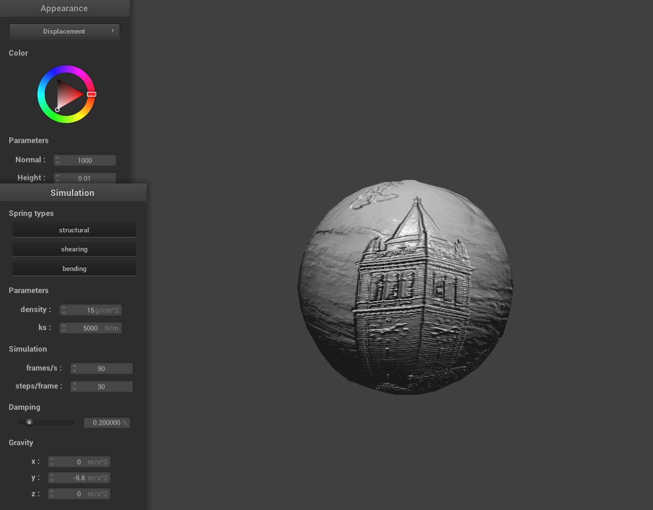
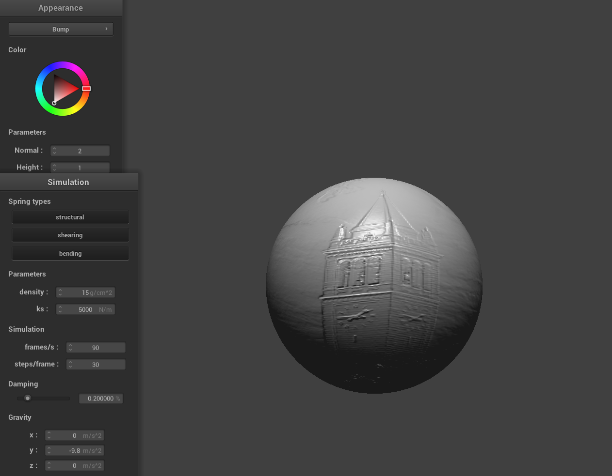
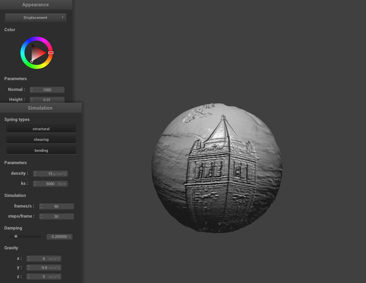
Here is a screenshot of bump mapping on the cloth and on the sphere and a screenshot of displacement mapping on the sphere using a texture image of Berkeley's Campanile.
|
|
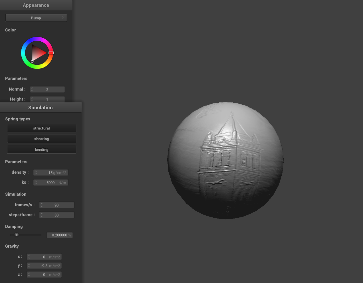
Bump mapping and displacement mapping are both techniques for simulating surface detail, but they work in fundamentally different ways. With bump mapping, detailed surface features are simulated by perturbing the surface normals used in lighting calculations without altering the actual geometry. In contrast, displacement mapping modifies the actual positions of the vertices based on a texture. This means that the surface geometry itself is altered, creating real, physical depth. We can clearly see this phenomenon above with the displacement sphere's geometry actually warped.
We can also change the sphere mesh's coarseness by using -o 16 -a 16 and then -o 128 -a 128. Visually, bump mapping seems to perform better than displacement mapping for this low sampling rate but as we increase the sample rate displacement mapping while a more computationally expensive task, it can better capture the texture associated perturbations.
|
|
|
|
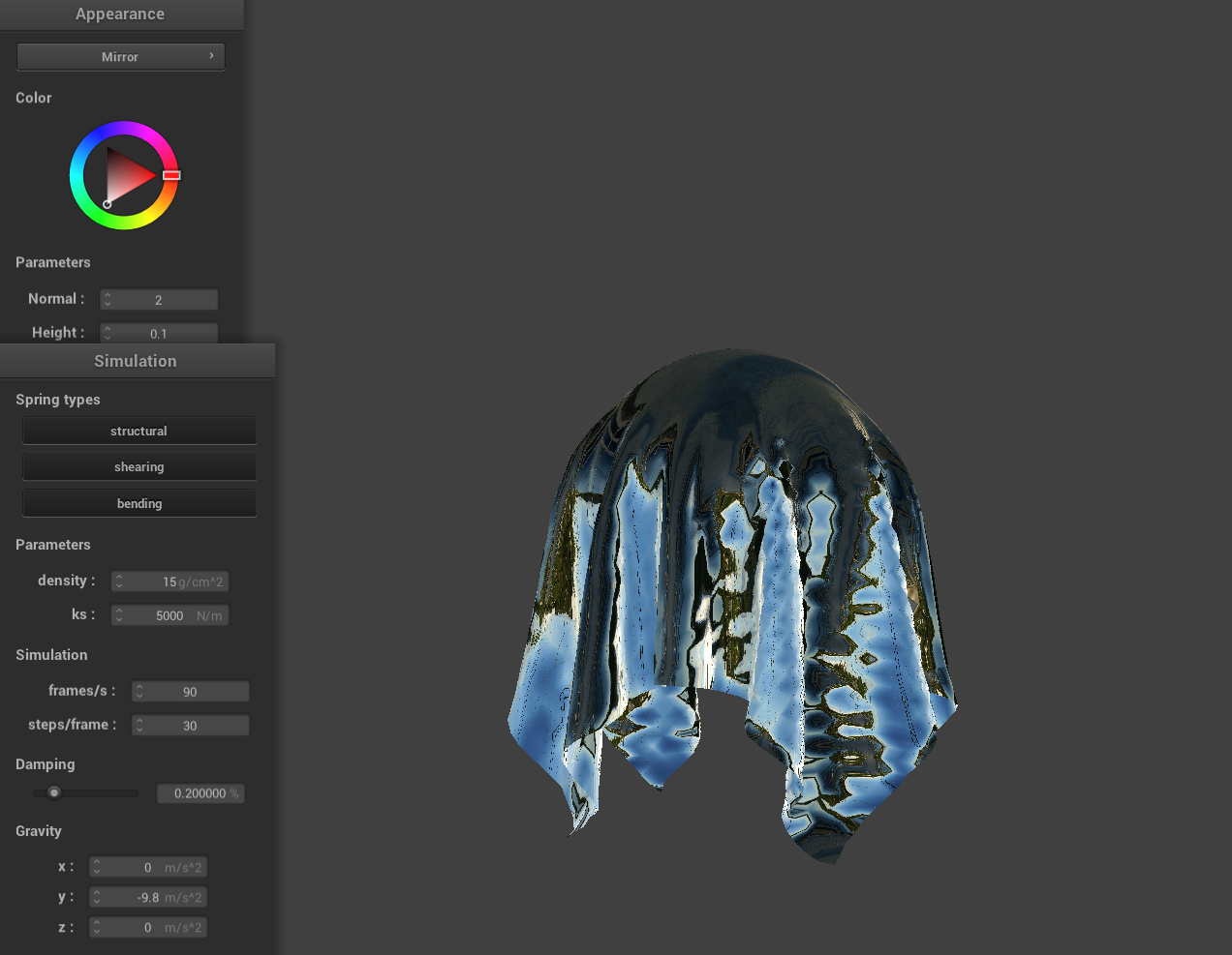
Mirror Shader
|
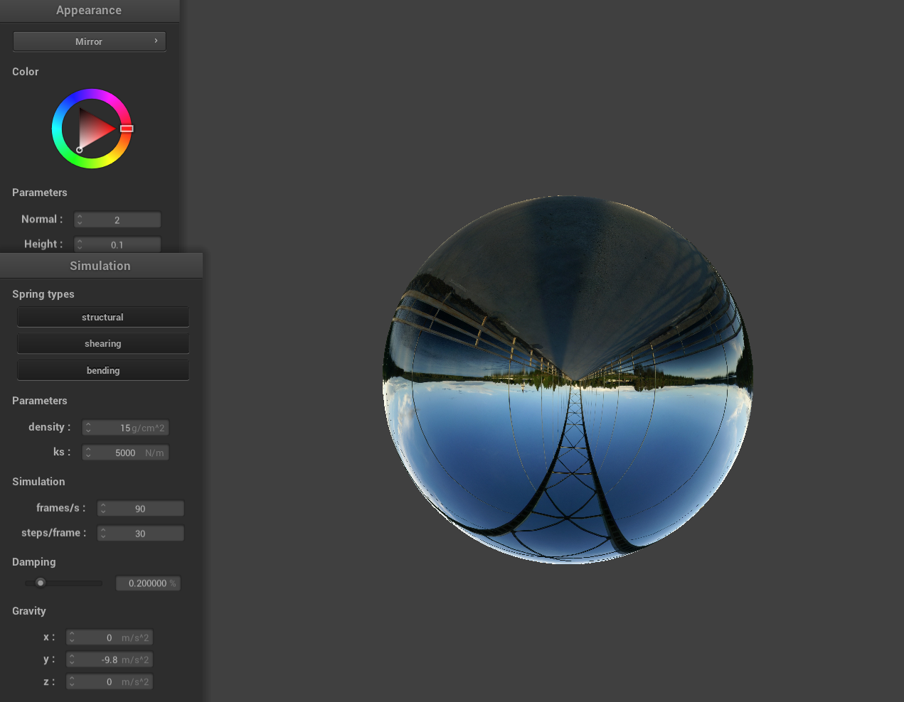
|
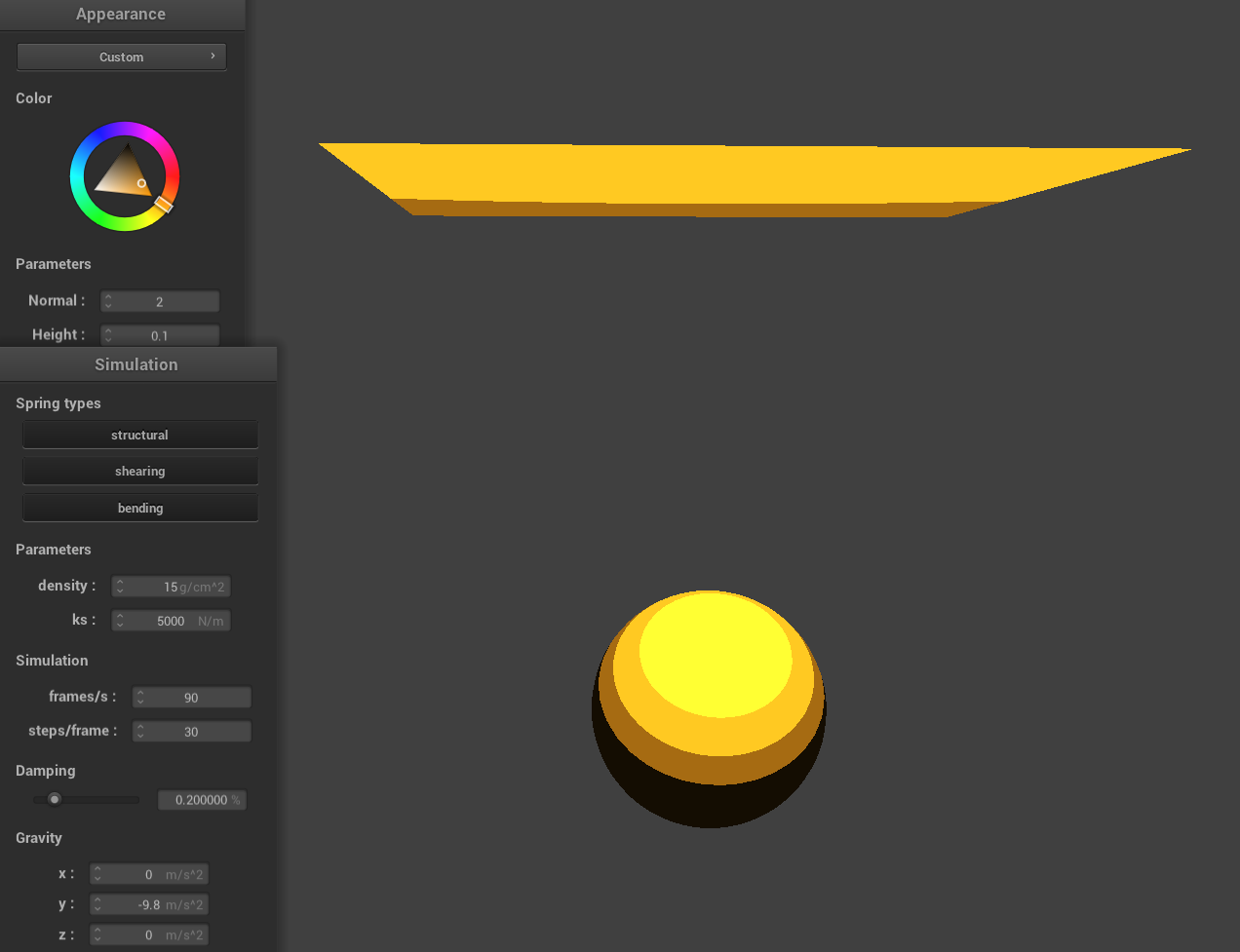
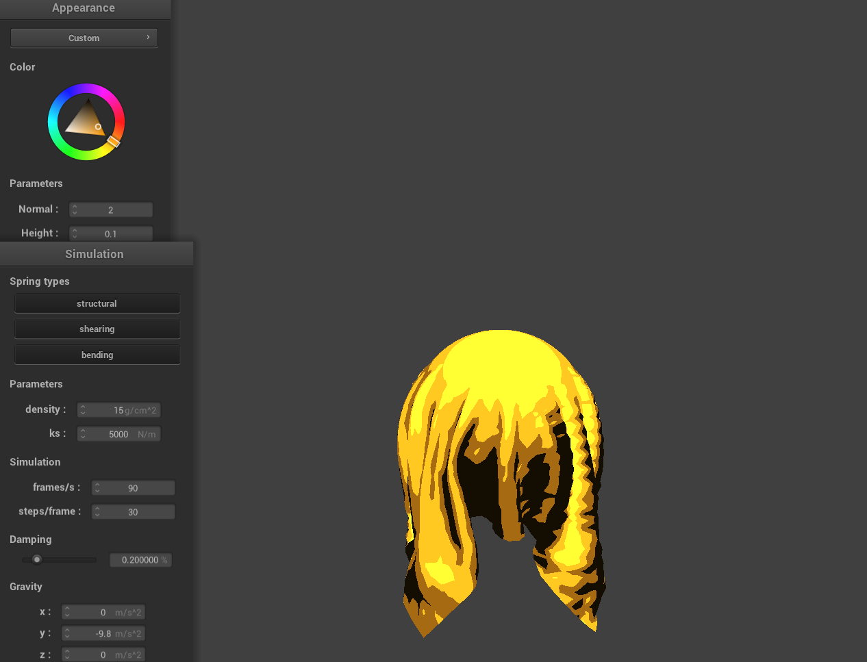
Cartoon Shader
I also decided to make an extra cartoon style shader where the diffuse light is calculated using the dot product between the normalized normal and the light direction, then quantized by multiplying by a preset number of levels, flooring the result, and finally dividing back. A small ambient factor (set here to 0.1) is added to prevent areas from becoming completely dark, and the final color is computed by multiplying the base color with the combined lighting which can be changed using the color wheel.
|
|